Screw Conveyor Horsepower
The calculations included in the KWS Screw Conveyor Engineering Guide are for control fed screw conveyors only. The horsepower calculations for screw feeders require additional considerations. Please consult KWS Engineering for screw feeder applications.
Horsepower is defined as the power required to safely and feasibly convey a bulk material a fixed distance in a screw conveyor. The horsepower required to drive a screw conveyor is called Total Shaft Horsepower, or TSHP.
TSHP is a function of the characteristics of the bulk material being conveyed and the friction inherent in the screw conveyor. It is very important to design a screw conveyor with sufficient horsepower in order to prevent downtime and loss of production.
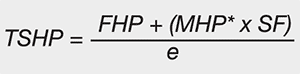
Properly defining the bulk material to be conveyed is very important because material characteristics such as bulk density, abrasiveness and flowability all play a role in determining the proper horsepower for a screw conveyor. TSHP is the sum of Friction Horsepower and Material Horsepower divided by the drive efficiency.
Friction Horsepower is the horsepower required to turn a screw conveyor when empty. Friction from the bearings, seals and other moving components create resistance. Sufficient horsepower is required to overcome the friction. Material Horsepower is the horsepower required to convey the bulk material the full length of the screw conveyor. The Friction and Material Horsepower calculations are shown below:
Friction HP Calculation:
Material HP Calculation:
Total Shaft HP Calculation:
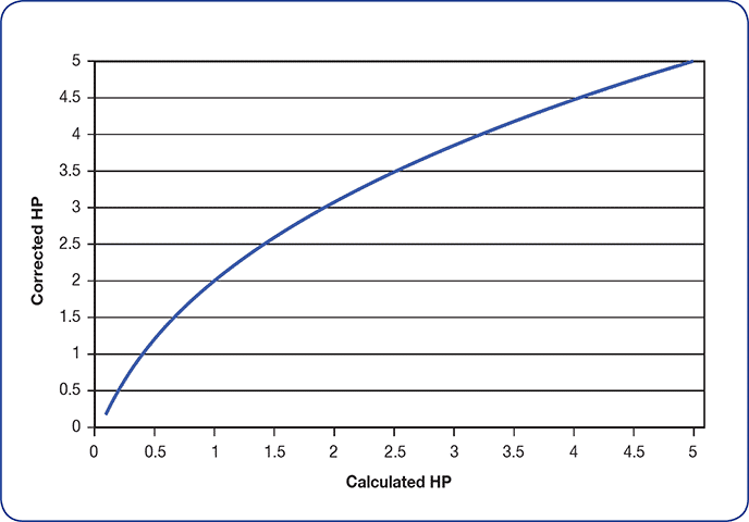
* If calculated Material Horsepower is less than 5HP
it should be corrected for potential overload.
Use the Corrected Material HP Chart.
Equation Nomenclature:
FHP = F riction HP (HP required to drive
conveyor empty)
DF = Conveyor Diameter Factor
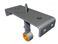
HBF = Hanger Bearing Factor
L = Conveyor Length (feet)
S = Conveyor Speed (RPM)
MHP = Material HP (HP required to convey bulk material)
CFH = Conveyor Capacity (ft3/hr)
W = Bulk Density (lbs/ft3)
MF = Material Factor (From Bulk Material Table)
CP = Capacity (lbs/hr)
TSHP = Total Shaft HP
e = Drive Efficiency (Typical value of 0.88 is
used for a shaft mount reducer/motor)
The Diameter Factor (DF) is an empirical value determined over many years of testing and represents the frictional resistance of the weight of the screw for various screw diameters.
| Diameter factor Table (df) | |
|---|---|
| Dia. | Factor |
| 4 | 12 |
| 6 | 18 |
| 9 | 31 |
| 12 | 55 |
| 14 | 78 |
| 16 | 106 |
| 18 | 135 |
| 20 | 165 |
| 24 | 235 |
| 30 | 377 |
| 36 | 549 |
The Hanger Bearing Factor (HBF) is an empirical value determined over many years of testing and represents the frictional resistance of the hanger bearing for various types of hanger bearing materials.
| Hanger Bearing Factor Table (HBF) | |
|---|---|
| Bearing Type | Bearing factor |
| Ball, roller, or none | 1.0 |
| Bronze, or wood | 1.7 |
| plastic, nylon, UHMw, or Teflon | 2.0 |
| Hard iron, or Stellite | 4.4 |
The Material Factor (MF) is an empirical value determined over many years of testing and represents the frictional resistance of the bulk material being conveyed. Please note that as the bulk density increases, typically the Material Factor increases because denser bulk materials are more difficult to convey. Material Factors for many materials can be found in the Bulk Material Table.
The drive unit for a screw conveyor is typically designed with a gear reducer and motor. The drive unit for a screw conveyor is not 100-percent efficient. There are frictional losses in the gear reducer and belt/chain reduction. Drive efficiency (e) is typically between 85 and 95-percent.
Corrected Material Horsepower
The calculated horsepower of a screw conveyor may need to be adjusted so the drive unit will have more horsepower and torque available to overcome an upset condition such as a minor choke in the inlet or a large lump being conveyed.
The Corrected Material Horsepower Factor, sometimes called the Overload Factor, is used to increase the Total Shaft Horsepower (TSHP) of a screw conveyor when the calculated Material Horsepower (MHP) is less than 5-HP. Increasing the TSHP allows the screw conveyor to overcome most upset conditions, reducing downtime and loss of production.
Corrected Material HP Chart
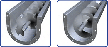
Conveyors With Special Flights
The procedure for calculating Total Shaft Horsepower (TSHP) for screw conveyors with special flights is identical to that used for standard flights except the Material Horsepower (MHP) must be multiplied by one or more of the Special Flight Factors (SF).
Special Flight Factors are used to account for the additional horsepower needed to overcome the resistance of the special flights to the bulk material being conveyed. Special flights are used for chopping up or mixing bulk materials and additional horsepower is required to perform these functions.
Total Shaft Horsepower
* If calculated Material Horsepower is less than 5HP it should be corrected for potential overload. Use the Corrected Material HP Chart.
Special Flight Factors:
| Type | Conveyor Loading | ||
|---|---|---|---|
| 15% | 30% | 45% | |
| Cut flight | 1.10 | 1.15 | 1.2 |
| Cut & folded flight | X | 1.50 | 1.7 |
| ribbon flight | 1.05 | 1.14 | 1.20 |
| Paddles Per Pitch | 1 | 2 | 3 | 4 |
|---|---|---|---|---|
| Factor | 1 .29 | 1 .58 | 1 .87 | 2 .16 |
Note: Trough loading must not exceed 45-percent when using special flights.
Example
Using the previous example, a screw conveyor is required to transport 10 tons per hour of unslaked lime with a bulk density of 60 lbs. per cubic foot. The unslaked lime also needs to be mixed in transit using cut and folded flights. The conveying distance is 15-feet so short (2/3) pitch screws will be used to ensure proper mixing.
The recommended trough loading percentage from the Bulk Material Table is 30A. The Special Flight Factor for cut-and-folded flights at 30-percent trough loading is 1.50.
| Type | Conveyor Loading | ||
|---|---|---|---|
| 15% | 30% | 45% | |
| Cut flight | 1.10 | 1.15 | 1.2 |
| Cut & folded flight | X | 1.50 | 1.7 |
| Ribbon flight | 1.05 | 1.14 | 1.20 |
The Material Horsepower (MHP) will be multiplied by 1.50 to account for the additional horsepower needed to overcome the resistance of the special flights to the unslaked lime being conveyed and mixed.