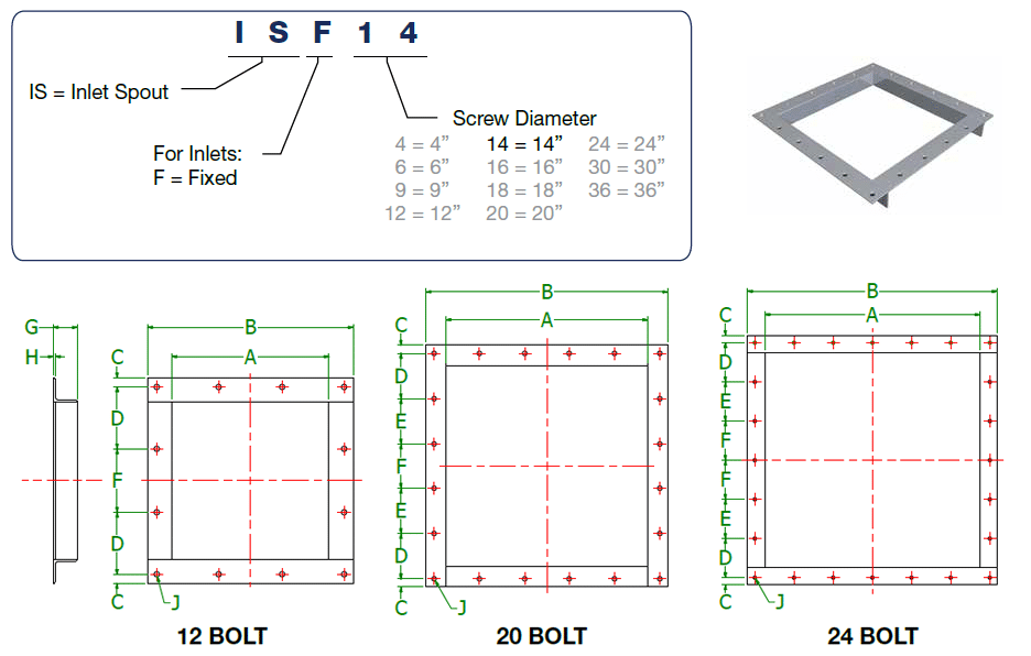
Screw Conveyor Inlet Spouts
Inlet spouts are typically located at one end of a screw conveyor on the top of the cover. Bulk materials enter a screw conveyor through the inlet spout. Multiple inlet spouts can be used to feed a screw conveyor. The screw conveyor must be designed for the total volumetric feed rate of all of the inlets combined.
Nomenclature

| Screw Dia. |
A | B | C | D | E | F | G | H | J | Part Number |
Weight (Lbs.) |
|||
|---|---|---|---|---|---|---|---|---|---|---|---|---|---|---|
| Inlets | Discharges | Inlets | Discharges | Qty. | Bolt Dia. | |||||||||
| 4” | 5” | 7-1/2” | 7-1/2” | 3/8” | 3/8” | 2-1/4” | X | 2-1/4” | 1-1/4” | 1/8” | 12 | 1/4” | ISF4* | 2 |
| 6” | 7” | 10” | 10” | 11/16” | 11/16” | 2-13/16” | X | 3” | 1-1/2” | 3/16” | 12 | 3/8” | ISF6* | 5 |
| 9” | 10” | 13” | 13-1/4” | 1/2” | 5/8” | 4” | X | 4” | 1-1/2” | 3/16” | 12 | 3/8” | ISF9* | 7 |
| 12” | 13” | 17” | 17-1/4” | 3/4” | 7/8” | 5-1/8” | X | 5-1/4” | 2” | 3/16” | 12 | 3/8” | ISF12* | 12 |
| 14” | 15” | 19” | 19-1/4” | 3/4” | 7/8” | 3-1/2” | 3-1/2” | 3-1/2” | 2” | 3/16” | 20 | 3/8” | ISF14* | 14 |
| 16” | 17” | 21” | 21-1/4” | 3/4” | 7/8” | 3-3/4” | 4” | 4” | 2” | 1/4” | 20 | 3/8” | ISF16* | 15 |
| 18” | 19” | 24” | 24-1/4” | 1” | 1-1/8” | 4-7/16” | 4-3/8” | 4-3/8” | 2-1/2” | 1/4” | 20 | 1/2” | ISF18* | 29 |
| 20” | 21” | 26” | 26-1/4” | 1” | 1-1/8” | 4-7/8” | 4-3/4” | 4-3/4” | 2-1/2” | 1/4” | 20 | 1/2” | ISF20* | 32 |
| 24” | 25” | 30” | 30-1/4” | 1” | 1-1/8” | 5-5/8” | 5-5/8” | 5-1/2” | 2-1/2” | 1/4” | 20 | 1/2” | ISF24* | 37 |
| 30” | 31” | 37” | 36-1/4” | 1-1/4” | 1-3/8” | 5-3/4” | 5-3/4” | 5-3/4” | 3” | 3/8” | 24 | 1/2” | ISF30 | 62 |
| 36” | 37” | 43” | 43-1/4” | 1-1/4” | 1-3/8” | 6-3/4” | 6-3/4” | 6-3/4” | 3” | 3/4” | 24 | 1/2” | ISF36 | 73 |
* KWS Stock Component (Only Includes Fixed Inlets) Note: Above table gives dimensions for the Discharge Flanges also.


