Screw Conveyor Covers
Covers are placed over the trough and fastened in place to provide a FIXED enclosure for the bulk material and to provide protection for personnel operating and maintaining the equipment. Standard cover lengths are 10-feet for 4, 6, and 9-inch diameter screw conveyors. Standard cover lengths are 12-feet for screw conveyors 12-inch and larger in diameter. KWS recommends bolting all covers on close centers to prevent access to the screw during operation.
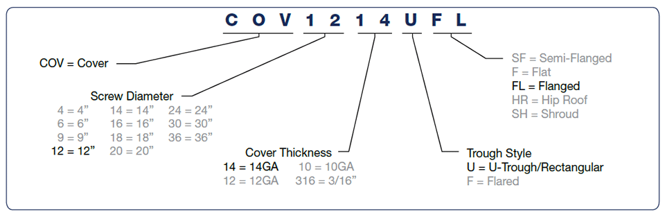
Nomenclature
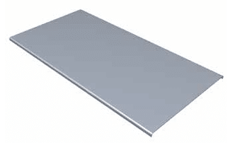
Flanged
Flanged covers are manufactured with formed flanges on each side to provide extra rigidity. KWS recommends using flanged covers with U, flared and rectangular troughs because covers are held in place by the formed flanges on each side. KWS recommends bolting all covers on close centers to prevent access to the screw during operation.
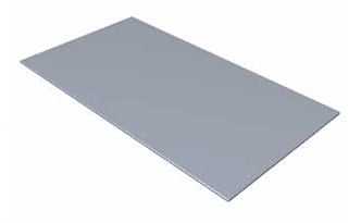
Flat
Flat covers are manufactured from thin gauge flat metal and do not have the rigidity of flanged covers. KWS does not recommend the use of flat covers because flat covers can easily slide off the top of a screw conveyor and cause injury to personnel. KWS recommends bolting all covers on close centers to prevent access to the screw during operation.
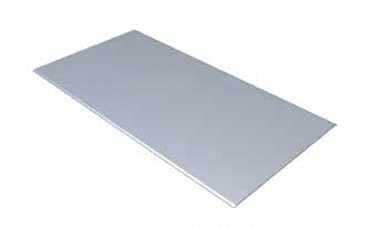
Semi-Flanged
Semi-flanged covers are manufactured with a slight formed flange on each side to provide some rigidity. KWS recommends flanged covers in place of semi-flanged covers in most applications. Cover sections are typically secured using spring clamps. KWS recommends bolting all covers on close centers to prevent access to the screw during operation.
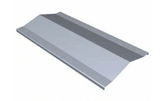
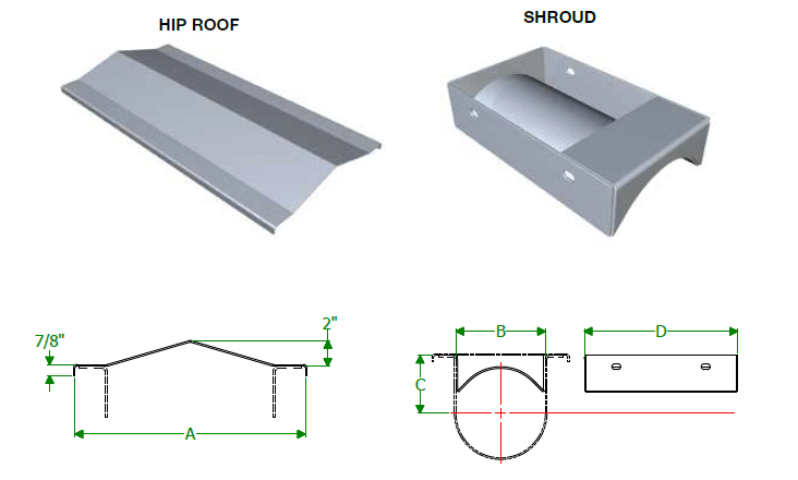
Hip Roof
Hip roof or ridged covers are manufactured with a center peak for outdoor applications. Snow or rain runs off the hip roof cover similar to a roof on a house. Formed flanges on both sides of the cover provide extra rigidity. KWS recommends bolting all covers on close centers to prevent access to the screw during operation.
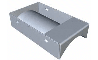
Shroud
Shrouds are manufactured to fit in U, flared or rectangular troughs and create a tubular cross section for screw feeders and steeply inclined screw conveyors. Standard covers can be used with shrouds. Shrouds are bolted on both sides of the trough for easy removal and include an integrated batten bar.
Covers

| Screw Dia. |
Cover Thk. |
A • (Approx) |
B • | C • | Semi-Flanged | Flanged | Flat | |||
|---|---|---|---|---|---|---|---|---|---|---|
| Part Number | Wt. (Lbs.) |
Part Number | Wt. (Lbs.) |
Part Number | Wt. (Lbs.) |
|||||
| 4” | 14 Ga. | 8-3/8” | 8” | 7-3/4” | COV414#SF | 2 | COV414#FL* | 3 | COV414#F | 2 |
| 6” | 14 Ga. | 10-7/8” | 10-1/2” | 9-3/4” | COV614#SF | 3 | COV614#FL* | 4 | COV614#F | 2 |
| 9” | 14 Ga. 12 Ga. |
14-3/8” | 14” | 13-1/4” | COV914#SF COV912#SF |
4 5 |
COV914#FL* COV912#FL |
5 7 |
COV914#F COV912#F |
3 6 |
| 12” | 14 Ga. 12 Ga. |
18-1/4” | 18” | 17-1/4” | COV1214#SF COV1212#SF |
5 7 |
COV1214#FL* COV1212#FL |
6 8 |
COV1214#F COV1212#F |
5 8 |
| 14” | 14 Ga. 12 Ga. |
20-1/4” | 20” | 19-1/4” | COV1414#SF COV1412#SF |
6 8 |
COV1414#FL* COV1412#FL |
6 9 |
COV1414#F COV1412#F |
5 9 |
| 16” | 14 Ga. 12 Ga. |
22-1/4” | 22” | 21-1/4” | COV1614#SF COV1612#SF |
6 9 |
COV1614#FL* COV1612#FL |
7 10 |
COV1614#F COV1612#F |
6 10 |
| 18” | 12 Ga. 10 Ga. |
25-1/4” | 25” | 24-1/4” | COV1812#SF COV1810#SF |
10 14 |
COV1812#FL COV1810#FL* |
11 14 |
COV1812#F COV1810#F |
6 11 |
| 20” | 12 Ga. 10 Ga. |
27-1/4” | 27” | 26-1/4” | COV2012#SF COV2010#SF |
11 15 |
COV2012#FL COV2010#FL* |
12 15 |
COV2012#F COV2010#F |
7 12 |
| 24” | 12 Ga. 10 Ga. |
31-1/4” | 31” | 30-1/4” | COV2412#SF COV2410#SF |
12 17 |
COV2412#FL COV2410#FL* |
14 18 |
COV2412#F COV2410#F |
11 14 |
| 30” | 10 Ga. | 39-3/8” | 39” | 38-1/2” | COV3010#SF | 21 | COV3010#FL | 22 | COV3010#F | 21 |
| 36” | 3/16” | 45-3/8” | 45” | 44-1/2” | COV36316#SF | 32 | COV36316#FL | 33 | COV36316#F | 32 |
* KWS Stock Component (U-Troughs only) • Dimensions will change for flared troughs
# Trough Style: U = U-Trough/Rectangular, F = Flared
| Screw Dia. |
Cover Thk. |
A • | B • | C • | D | Hip Roof | Shroud | ||
|---|---|---|---|---|---|---|---|---|---|
| Part Number | Wt. /Ft. (Lbs.) |
Part Number | Wt. /Ft. (Lbs.) |
||||||
| 4” | 14 Ga. | 8” | 5” | 3-5/8” | 8” | COV414#HR | 2 | N/A | |
| 6” | 14 Ga. 12 Ga. |
10-1/2” | 7” | 4-1/2” | 12” | COV614#HR COV612#HR |
4 4 |
N/A COV612#SH* |
8 |
| 9” | 14 Ga. 12 Ga. 3/16” |
14” | 10” | 6-1/8” | 18” | COV914#HR COV912#HR X |
4 6 X |
N/A N/A COV9316#SH* |
23 |
| 12” | 14 Ga. 10 Ga 3/16” |
18” | 13” | 7-3/4” | 24” | COV1214#HR COV1210#HR X |
5 10 X |
N/A N/A COV12316#SH* |
41 |
| 14” | 14 Ga. 10 Ga. 3/16” |
20” | 15” | 9-1/4” | 28” | COV1414#HR COV1410#HR X |
6 11 X |
N/A N/A COV14316#SH* |
60 |
| 16” | 14 Ga. 10 Ga. 3/16” |
22” | 17” | 10-5/8” | 32” | COV1614#HR COV1610#HR X |
7 12 X |
N/A N/A COV16316#SH* |
78 |
| 18” | 12 Ga. 10 Ga. 3/16” |
25” | 19” | 12-1/8” | 36” | COV1812#HR COV1810#HR X |
10 12 X |
N/A N/A COV18316#SH* |
98 |
| 20” | 12 Ga. 10 Ga. 3/16” |
27” | 21” | 13-1/2” | 40” | COV2012#HR COV2010#HR X |
11 15 X |
N/A N/A COV20316#SH* |
114 |
| 24” | 12 Ga. 10 Ga. 3/16” |
31” | 25” | 16-1/2” | 48” | COV2412#HR COV2410#HR X |
14 19 X |
N/A N/A COV24316#SH* |
175 |
| 30” | 10 Ga. 3/16” 1/4” |
39” | 31” | 20-1/4” | 60” | COV3010#HR X X |
25 | N/A N/A COV30250#SH |
290 |
| 36” | 3/16” 1/4” |
45” | 37” | 24-3/8” | 72” | COV36316#HR X |
36 | N/A COV36250#SH |
330 |
* KWS Stock Component (U-Troughs only) • Dimensions will change for flared troughs
# Trough Style: U = U-Trough/Rectangular, F = Flared