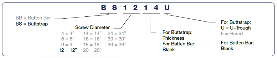
Screw Conveyor Buttstraps and Batten Bars
Buttstraps fit over the top of the joint between two cover sections. Gasket material is used under the buttstrap to provide a sealed design. The buttstrap is bolted on both sides through the cover and trough flange to create a dust-tight enclosure.
Batten bars are mounted flush with the top of the trough flange and fit under the joint between two cover sections. Gasket material is used over the batten bar to provide a seal. Batten bars can be provided with weld studs or rivnuts for securing the cover sections to the batten bar to create a dust-tight enclosure.
Nomenclature
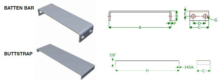
| Screw Dia. |
A | B | C | D | E | F | G Bolts |
H | Buttstrap | Batten Bar | ||
|---|---|---|---|---|---|---|---|---|---|---|---|---|
| Part Number |
Weight (Lbs.) |
Part Number |
Weight (Lbs.) |
|||||||||
| 4” | 5” | 1” | 3” | 2” | 5/8” | 3/16” | 3/8” | 8-3/8” | BS4#@ | 1 | BB4 | 1 |
| 6” | 7” | 1-1/4” | 3” | 2” | 3/4” | 3/16” | 3/8” | 10-7/8” | BS6#@ | 1 | BB6 | 2 |
| 9” | 10” | 1-1/2” | 4” | 2-1/2” | 7/8” | 1/4” | 1/2” | 14-3/8” | BS9#@ | 1 | BB9 | 4 |
| 12” | 13” | 2” | 4” | 2-1/2” | 1-1/8” | 1/4” | 5/8” | 18-3/8” | BS12#@ | 2 | BB12 | 5 |
| 14” | 15” | 2” | 4” | 2-1/2” | 1-1/8” | 1/4” | 5/8” | 20-3/8” | BS14#@ | 2 | BB14 | 6 |
| 16” | 17” | 2” | 5” | 2-1/2” | 1-1/8” | 3/8” | 5/8” | 22-3/8” | BS16#@ | 2 | BB16 | 11 |
| 18” | 19” | 2-1/2” | 5” | 3-1/2” | 1-3/8” | 3/8” | 5/8” | 25-3/8” | BS18#@ | 3 | BB18 | 13 |
| 20” | 21” | 2-1/2” | 5” | 3-1/2” | 1-3/8” | 3/8” | 3/4” | 27-3/8” | BS20#@ | 4 | BB20 | 14 |
| 24” | 25” | 2-1/2” | 5” | 3-1/2” | 1-3/8” | 3/8” | 3/4” | 31-3/8” | BS24#@ | 4 | BB24 | 17 |
| 30” | 31” | 3” | 6” | 3-1/2” | 1-3/4” | 1/4” | 3/4” | 39-3/8” | BS30#@ | 7 | BB30 • | 27 |
| 36” | 37” | 3” | 6” | 3-1/2” | 1-3/4” | 1/4” | 3/4” | 45-3/8” | BS36#@ | 7 | BB36 • | 32 |
• Requires a Formed Channel Support Bar # = Thickness Note: Dimensions in the above table are for U-Troughs only.
@ = Trough Type: U = U-Trough, F = Flared