Screw Conveyor Hangers
U-Trough Hangers Flared Trough HangersHangers are intermediate support brackets located between screw sections along the length of a screw conveyor. Hangers allow for the use of multiple screw sections. Many different hanger styles are available, depending on the application. Style 216 and 226 hangers are the most widely used and are in stock at KWS. Hangers are generally used when conveying non-abrasive and free-flowing bulk materials. The bulk material must be able to flow around the hanger. Hangers are not recommended when conveying abrasive and sluggish bulk materials.
Nomenclature

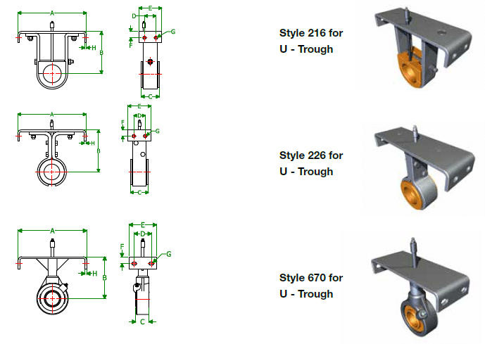
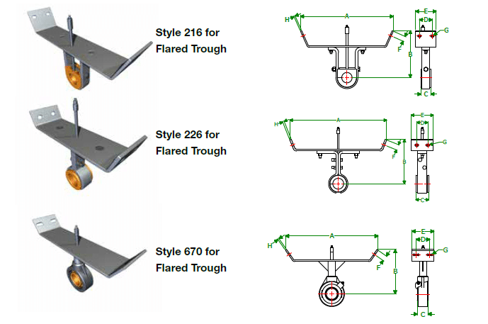
Style 216
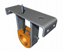
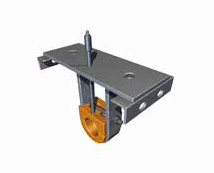
Style 216 hangers are an inside flush mounted hanger. The double body bar provides extra rigidity for heavier screw sections in more demanding applications. The flush mounted top bar bolts to the inside of the trough flanges and allows for the use of standard trough covers.
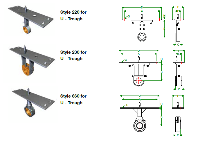
Style 220
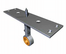
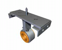
Style 220 hangers are a top mounted hanger. The combination body bar provides rigidity for light and medium duty applications while allowing minimal obstruction of material flow. The top mounted top bar bolts to the top of the trough flanges and requires the use of special covers.
Style 226
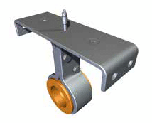
Style 226 hangers are an inside flush mounted hanger. The combination body bar provides rigidity for light and medium duty applications while allowing minimal obstruction of material flow. The flush mounted top bar bolts to the inside of the trough flanges and allows for the use of standard trough covers.
Style 230
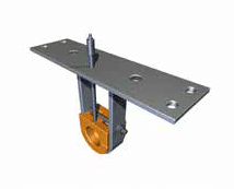
Style 230 hangers are a top mounted hanger. The double body bar provides extra rigidity for heavier screw sections in more demanding applications. The top mounted top bar bolts to the top of the trough flanges and requires the use of special covers.
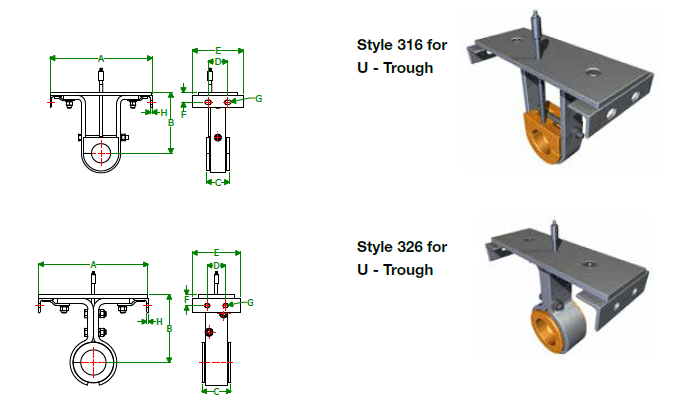
Style 316
Style 316 hangers are an inside flush mounted hanger. The top bar is self-adjusting to compensate for thermal expansion in high temperature applications. The double body bar provides extra rigidity for heavier screw sections in more demanding applications. The flush mounted top bar bolts to the inside of the trough flanges and allows for the use of standard trough covers.
Style 326
Style 326 hangers are an inside flush mounted hanger. The top bar is self-adjusting to compensate for thermal expansion in high temperature applications. The combination body bar provides rigidity for light and medium duty applications while allowing minimal obstruction of material flow. The flush mounted top bar bolts to the inside of the trough flanges and allows for the use of standard trough covers.
Style 660
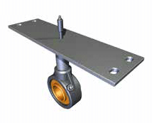
Style 660 hangers are a top mounted hanger. Supplied with a dust-tight sealed ball bearing, style 660 hangers allow for 4-degrees of shaft misalignment and temperatures up to 240-degrees F. The pipe body bar provides rigidity for light and medium duty applications while allowing minimal obstruction of material flow. The top-mounted top bar bolts to the top of the trough flanges and requires the use of special covers.
Style 670
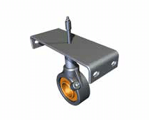
Style 670 hangers are an inside flush mounted hanger. Supplied with a dust-tight sealed ball bearing, style 670 hangers allow for 4-degrees of shaft misalignment and temperatures up to 240-degrees F. The pipe body bar provides rigidity for light and medium duty applications while allowing minimal obstruction of material flow. The flush mounted top bar bolts to the inside of the trough flanges and allows for the use of standard trough covers.
U-Trough Hangers
| Screw Dia. | Shaft Dia. | A | B | C | D | E | F | G Bolts |
H | Part Number | Weight (Lbs.) | ||
|---|---|---|---|---|---|---|---|---|---|---|---|---|---|
| 216 | 226 | 670 | |||||||||||
| 4” | 1” | 5” | 3-5/8” | 1-1/2 | 2” | 4” | 5/8” | 1/4” | 3/16” | HGR4#1*†• | 3 | 5 | 5 |
| 6” | 1-1/2” | 7” | 4-1/2” | 2” | 2-1/2” | 4” | 3/4” | 3/8” | 1/4” | HGR6#112*@ | 5 | 7 | 7 |
| 9” | 1-1/2” 2” |
10” | 6-1/8” | 2” 2” |
2-1/2” | 4” | 1” | 3/8” | 1/4” | HGR9#112*@ HGR9#2*@ |
7 9 |
9 11 |
8 9 |
| 12” | 2” 2-7/16” 3” |
13” | 7-3/4” | 2” 3” 3” |
2-1/2” | 5” | 1-1/4” | 1/2” | 3/8” | HGR12#2*@ HGR12#2716*@ HGR12#3*@ |
14 18 21 |
16 21 28 |
12 20 30 |
| 14” | 2-7/16” 3” |
15” | 9-1/4” | 3” 3” |
2-1/2” | 5” | 1-3/8” | 1/2” | 3/8” | HGR14#2716*@ HGR14#3*@ |
23 25 |
22 26 |
21 32 |
| 16” | 3” | 17” | 10-5/8” | 3” | 2-1/2” | 5” | 1-3/8” | 1/2” | 3/8” | HGR16#3*@ | 28 | 39 | 35 |
| 18” | 3” 3-7/16” |
19” | 12-1/8” | 3” 4” |
3-1/2” | 5” | 1-5/8” | 5/8” | 1/2” | HGR18#3*@ HGR18#3716*@ |
34 44 |
41 49 |
40 46 |
| 20” | 3” 3-7/16” |
21” | 13-1/2” | 3” 4” |
3-1/2” | 5” | 1-5/8” | 5/8” | 1/2” | HGR20#3*@ HGR20#3716*@ |
36 47 |
43 51 |
45 52 |
| 24” | 3-7/16” | 25” | 16-1/2” | 4” | 3-1/2” | 5” | 1-3/4” | 5/8” | 1/2” | HGR24#3716*@ | 53 | 67 | 63 |
| 30” | 3-15/16” | 31” | 19-1/2” | 4” | 3-1/2” | 5-1/2” | 1-3/4” | 3/4” | 1/2” | HGR30#31516•@ | 68 | 79 | 68 |
| 36” | 4-7/16” | 37” | 22-1/2” | 5” | 3-1/2” | 5-1/2” | 1-3/4” | 3/4” | 1/2” | HGR36#4716•@ | 83 | 88 | 83 |
* KWS Stock Component only for 216 and 226 standard style hangers # = 216, 226, or 670
† Not Available for Style 216 • Not Available for Style 670 @ = Blank=Standard, GP=Drilled for grease pipe
| Screw Dia. | Shaft Dia. | A | B | C | D | E | F | G Bolts |
H | Part Number | Weight (Lbs.) | ||
|---|---|---|---|---|---|---|---|---|---|---|---|---|---|
| 220 | 230 | 660 | |||||||||||
| 4” | 1” | 6-1/4” | 3-5/8” | 1-1/2” | 7-1/4” | 2” | 4” | 1/4” | 1/4” | HGR4#1†• | 5 | 5 | 5 |
| 6” | 1-1/2” | 8-3/4” | 4-1/2” | 2” | 9-3/4” | 2-1/2” | 4” | 3/8” | 1/4” | HGR6#112@ | 7 | 7 | 7 |
| 9” | 1-1/2” 2” |
12-1/4” | 6-1/8” | 2” 2” |
13-1/2” | 2-1/2” | 4” | 3/8” | 1/4” | HGR9#112@ HGR9#2@ |
9 11 |
9 11 |
8 9 |
| 12” | 2” 2-7/16” 3” |
15-3/4” | 7-3/4” | 2” 3” 3” |
17-1/2” | 2-1/2” | 5” | 1/2” | 3/8” | HGR12#2@ HGR12#2716@ HGR12#3@ |
16 21 28 |
16 21 28 |
12 20 30 |
| 14” | 2-7/16” 3” |
17-3/4” | 9-1/4” | 3” 3” |
19-1/2” | 2-1/2” | 5” | 1/2” | 3/8” | HGR14#2716@ HGR14#3@ |
26 33 |
26 33 |
21 32 |
| 16” | 3” | 19-3/4” | 10-5/8” | 3” | 21-1/2” | 2-1/2” | 5” | 1/2” | 3/8” | HGR16#3@ | 39 | 39 | 35 |
| 18” | 3” 3-7/16” |
22-1/4” | 12-1/8” | 3” 4” |
24-1/2” | 3-1/2” | 5” | 5/8” | 1/2” | HGR18#3@ HGR18#3716@ |
41 49 |
41 49 |
40 46 |
| 20” | 3” 3-7/16” |
24-1/2” | 13-1/2” | 3” 4” |
26-1/2” | 3-1/2” | 5” | 5/8” | 1/2” | HGR20#3@ HGR20#3716@ |
43 51 |
43 51 |
45 58 |
| 24” | 3-7/16” | 28-1/4” | 16-1/2” | 4” | 30-1/2” | 3-1/2” | 5” | 5/8” | 1/2” | HGR24#3716@ | 67 | 67 | 69 |
| 30” | 3-15/16” | 36-1/4” | 19-1/2” | 4” | 38-1/2” | 3-1/2” | 5-1/2” | 3/4” | 1/2” | HGR30#31516•@ | 73 | 73 | 75 |
| 36” | 4-7/16” | 42-1/4” | 22-1/2” | 5” | 44-1/2” | 3-1/2” | 5-1/2” | 3/4” | 1/2” | HGR36#4716•@ | 88 | 88 | 91 |
# = 220, 230, or 660 † Not Available for Style 230 • Not Available for Style 660
@ = Blank=Standard, GP=Drilled for grease pipe
| Screw Dia. | Shaft Dia. | A | B | C | D | E | F | G Bolts |
H | Part Number | Weight (Lbs.) | |
|---|---|---|---|---|---|---|---|---|---|---|---|---|
| 220 | 230 | |||||||||||
| 4” | 1” | 5” | 3-5/8” | 1-1/2” | 2” | 5” | 5/8” | 1/4” | 1/8” | HGR4#1†@ | 5 | 5 |
| 6” | 1-1/2” | 7” | 4-1/2” | 2” | 2-1/2” | 6” | 3/4” | 3/8” | 1/8” | HGR6#112@ | 6 | 6 |
| 9” | 1-1/2” 2” |
10” | 6-1/8” | 2” 2” |
2-1/2” | 6” | 1” | 3/8” | 3/16” | HGR9#112@ HGR9#2@ |
8 10 |
8 10 |
| 12” | 2” 2-7/16” 3” |
13” | 7-3/4” | 2” 3” 3” |
2-1/2” | 6-1/2” | 1-1/4” | 1/2” | 3/16” | HGR12#2@ HGR12#2716@ HGR12#3@ |
15 20 25 |
15 20 25 |
| 14” | 2-7/16” 3” |
15” | 9-1/4” | 3” 3” |
2-1/2” | 6-1/2” | 1-3/8” | 1/2” | 1/4” | HGR14#2716@ HGR14#3@ |
24 31 |
24 29 |
| 16” | 3” | 17” | 10-5/8” | 3” | 2-1/2” | 6-1/2” | 1-3/8” | 1/2” | 1/4” | HGR16#3@ | 36 | 35 |
| 18” | 3” 3-7/16” |
19” | 12-1/8” | 3” 4” |
3-1/2” | 6-1/2” 7” |
1-5/8” | 5/8” | 1/4” | HGR18#3@ HGR18#3716@ |
36 48 |
34 47 |
| 20” | 3” 3-7/16” |
21” | 13-1/2” | 3” 4” |
3-1/2” | 6-1/2” 7” |
1-5/8” | 5/8” | 1/4” | HGR20#3@ HGR20#3716@ |
40 51 |
40 51 |
| 24” | 3-7/16” | 25” | 16-1/2” | 4” | 3-1/2” | 7” | 1-3/4” | 5/8” | 5/16” | HGR24#3716@ | 58 | 58 |
| 30” | 3-15/16” | 31” | 19-1/2” | 4” | 3-1/2” | 8” | 1-3/4” | 3/4” | 3/8” | HGR30#31516@ | 63 | 64 |
| 36” | 4-7/16” | 37” | 22-1/2” | 5” | 3-1/2” | 8” | 1-3/4” | 3/4” | 3/8” | HGR36#4716@ | 80 | 82 |
# = 316 or 326 † Not Available for Style 316 @ = Blank=Standard, GP=Drilled for grease pipe
Flared Trough Hangers
| Screw Dia. | Shaft Dia. | A | B | C | D | E | F | G Bolts |
H | Part Number | Weight (Lbs.) | ||
|---|---|---|---|---|---|---|---|---|---|---|---|---|---|
| 220 | 230 | 660 | |||||||||||
| 4” | NOT AVAILABLE | ||||||||||||
| 6” | 1-1/2” | 14” | 7” | 2” | 2-1/2” | 4” | 3/4” | 3/8” | 1/4” | HGR6#F112@ | 7 | 8 | 8 |
| 9” | 1-1/2” 2” |
18” | 9” | 2” 2” |
2-1/2” | 4” | 1” | 3/8” | 1/4” | HGR9#F112@ HGR9#F2@ |
8 10 |
10 13 |
9 11 |
| 12” | 2” 2-7/16” 3” |
22” | 10” | 2” 3” 3” |
2-1/2” | 5” | 1-1/4” | 1/2” | 3/8” | HGR12#F2@ HGR12#F2716@ HGR12#F3@ |
15 20 24 |
18 23 32 |
14 23 35 |
| 14” | 2-7/16” 3” |
24” | 11” | 3” 3” |
2-1/2” | 5” | 1-3/8” | 1/2” | 1/4 | HGR14#F2716†@ HGR14#F3†@ |
25 28 |
29 27 |
24 37 |
| 16” | 3” | 28” | 11-1/2” | 3” | 2-1/2” | 5” | 1-3/8” | 1/2” | 1/4 | HGR16#F3†@ | 31 | 43 | 49 |
| 18” | 3” 3-7/16” |
31” | 12-1/8” | 3” 4” |
3-1/2” | 6” | 1-5/8” | 5/8” | 3/8” | HGR18#F3†@ HGR18#F3716†@ |
37 50 |
45 55 |
45 52 |
| 20” | 3” 3-7/16” |
34” | 13-1/2” | 3” 4” |
3-1/2” | 6” | 1-5/8” | 5/8” | 3/8” | HGR20#F3†@ HGR20#F3716†@ |
39 53 |
47 57 |
50 58 |
| 24” | 3-7/16” | 40” | 16-1/2” | 4” | 3-1/2” | 6” | 1-5/8” | 5/8” | 3/8” | HGR24#F3716†@ | 59 | 73 | 69 |
| 30” | 3-15/16” | 47-3/8” | 19-1/2” | 4” | 3-1/2” | 7” | 1-5/8” | 3/4” | 1/2” | HGR30#F31516•† @ | 78 | 95 | 78 |
| 36” | 4-7/16” | 54-3/8” | 22-1/2” | 5” | 3-1/2” | 7” | 1-5/8” | 3/4” | 1/2” | HGR36#F4716•† @ | 95 | 117 | 95 |
# = 216, 226, or 670 † Requires Top Bar To Be Constructed From Channel • Not Available For Style 670
@ = Blank=Standard, GP=Drilled for grease pipe