Proper Installation of Screw Conveyors
Question
Our facility recently received several KWS screw conveyors for our material handling system. As our maintenance team has limited experience with this equipment, we are concerned about proper installation procedures. What are the critical steps we should follow to ensure our KWS screw conveyors are installed correctly for optimal performance and longevity?
Answer
Proper screw conveyor installation begins with thorough inspection upon receipt, checking all components against shipping documents and examining for damage.
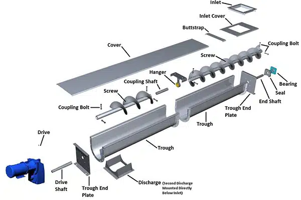
Exploded View Shows Screw Conveyor Components
For safe lifting and positioning, KWS specifically recommends using spreader bars with multiple slings to distribute weight evenly across the conveyor length during the lift. NEVER attempt to lift a conveyor with only one support point, as this will cause bending and component damage. Unsupported spans during lifting must not exceed 12 feet, and additional support points should be positioned near unusually heavy components such as drives and gates to maintain proper load balance and prevent distortion.
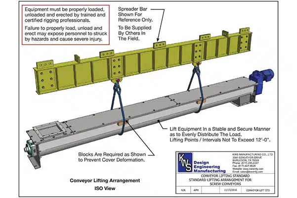
Proper Lifting Using Spreader Bar and Slings
Screw conveyors that are pre-assembled at KWS before shipment are match-marked for easier field assembly. Ensure mounting surfaces are level before positioning troughs in sequence with discharge spout properly located. Trough supports are located every 10 to 12 feet per CEMA recommendations.
Connect trough joints and trough ends loosely with fasteners only hand tight, then use a piano wire stretched along the centerline for alignment, ensuring maximum deviation of 1/8-inch horizontally and vertically before final tightening.
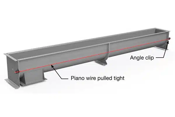
Piano Wire Stretched Along Centerline for Alignment
Using a level, check levelness along the length of the screw conveyor at each trough joint. Also, check levelness across each trough joint. Using both a piano wire and level will ensure proper installation of the trough assembly.
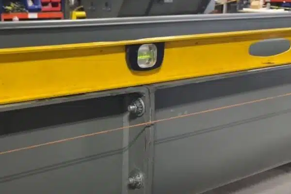
Use Level to Check Levelness at Each Trough Joint – Along Trough Joint
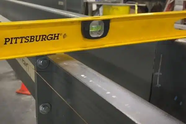
Use Level to Check Levelness at Each Trough Joint – Along Trough Joint
Trough fasteners must be tightened in an alternating pattern similar to tightening lug bolts on a vehicle’s wheel. As you tighten each trough fastener, make sure the trough sections remain in alignment and are level by checking with a tape measure and verifying level in both directions. Trough flanges can be easily manipulated with a hammer to gain proper trough alignment. All fasteners must be tightened to proper torque rating as shown in the KWS Operations and Maintenance Manual included with your order.
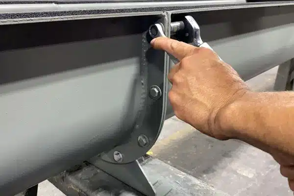
All Fasteners Must be Tightened to Proper Torque Rating
Mount drive unit (typically at discharge end), then install screw sections starting at the drive end with end lugs opposite the carrying side of flight. Maintain proper clearance between screw diameter and trough. Ensure 180-degree offset between adjoining screw sections. Center hanger bearings precisely between sections and torque all coupling bolts to 75% of specified values to prevent overtightening.
After installation, rotate the entire assembly by hand to check alignment, adjust seals as needed, and lubricate all bearings according to manufacturer specifications. Remember that drives are generally shipped without oil. Finally, install all covers in sequence and verify all safety labels are properly positioned before operation.
Reference the entire KWS Installation, Operation, and Maintenance Manual prior to starting any screw conveyor installation or maintenance projects.
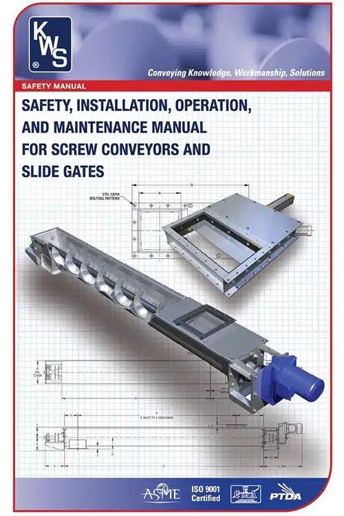
KWS Operations and Maintenance Manual is Readily Available


