Fatigue Failures in Screw Conveyors
Download PDFQuestion
I have a 16-inch diameter by 18-foot long screw conveyor in my plant conveying conditioned flyash. My screw conveyor is fed by a pugmill. The pugmill is mixing or conditioning the flyash with water to reduce dust as it is loaded into containers. The 16-inch diameter screw is a one-piece screw and is mounted on 6-inch schedule 80 pipe. The screw is very heavy-duty but we have continuous problems with it because the center pipe fails almost exactly at mid-span of the screw.
The downtime is hurting my productivity. Why is this screw failing and how can I prevent it from happening again?
Answer
Excellent question! Your problem is not uncommon and there are multiple solutions to prevent this problem from reoccurring. Most bulk materials are easily conveyed using screw conveyors, but some bulk materials have a tendency to pack under the pressure while being conveyed.
As a screw conveyor rotates, bulk materials are moved forward with each revolution of the screw. There is a gap between the outside diameter of the screw and the inside diameter of the trough or housing. Bulk materials fill this gap and form a layer between the screw and housing. As the screw rotates, the screw flight shears through the bulk materials in the gap. This shearing action puts pressure on the bulk material.
Bulk materials that have a tendency to pack will form a hard layer in the bottom of the housing. Most of the time the layer will break loose in chunks and be conveyed downstream. Repetitively, a new layer will form and then break loose again.
In very rare applications a bulk material will form a permanent layer in the bottom of the housing. This layer will build up over time and cause the screw to deflect in the center. Because each end of the screw is held fixed by the bearings, as the screw is pushed up in the center, enormous cyclical forces are imparted on the center pipe of the screw as it rotates. Every revolution of the screw causes a complete reversal of the forces on the center pipe.
This condition is very similar to taking a piece of wire and bending it back and forth until it breaks or fatigues. Most fatigue failures are easy to identify because the break is almost perpendicular to the centerline of the screw conveyor and the location of the fatigue failure is typically in the center of the screw section as shown in Figure 1.
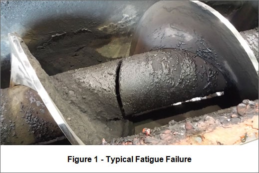
In your application you are adding water to the flyash, which is making the problem worse. The flyash/water combination is sluggish to convey and sticks to the bottom of the housing. It hardens like concrete and builds up. The outside diameter of the screw flights will become shiny as they wear against the layer of material in the trough as shown in Figure 1. This is a key indicator that you have buildup. In some extremely abrasive applications the outside diameter of the flights will actually wear down, causing excessive horsepower draw and screw failure.
The root cause of the problem is the buildup of hardened material in the bottom of the housing. This hardened material must be eliminated or reduced in order prevent screw conveyor failure. One solution is to add trough liners to reduce the gap between the outside diameter of the screw and the housing. If the layer of material is very thin, then it will break loose and be conveyed downstream. I would recommend using ¼-inch thick abrasion resistant plate for the liner material. The abrasion resistant plate will wear longer than mild steel.
Another solution is to mount the screw on larger diameter pipe with a heavier wall thickness. Currently, the screw is mounted on 6-inch schedule 80 pipe. This design is perfectly acceptable for almost every application because the screw deflection is minimal. Based on the information provided about the material buildup, using a more rigid screw would help solve the problem. I would suggest using 8-inch schedule 120 pipe with a 0.72-inch wall thickness. Larger, thicker pipe will provide extra rigidity and greater resistance to being pushed up in the housing.
Additionally, adding cutter teeth or weld-on hardsurfacing to the outside diameter of the screw flights would reduce the gap between the screw and housing as well as provide a cutting surface to cut through the hardened layer. Carbide cutting teeth can be added to the outside diameter of the screw and will cut through almost any hardened material in the housing.
As stated previously, the key to solving the problem is removing the hardened material in the bottom of the housing. The combination of adding liners along with either mounting the screw on larger pipe or adding cutter teeth will most certainly solve almost any problem of this type.