Get The Most From Your Screw Conveyor
Chemical Processing — September 1, 2020
By Jim Collins, KWS Manufacturing, and Aaron Mire, Motion Industries
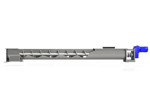
Typical Shafted Screw Conveyor
Figure 1. Although developed in antiquity, the design suits myriad modern applications. Source: KWS Manufacturing.
What Archimedes created centuries ago is still one of the most versatile means available to processors for providing enclosed transfer of materials. Indeed, Archimedes’ screw forms the foundation for devices conveying thousands of products, ranging from dry and free-flowing to wet, sticky and sluggish. While moving materials horizontally, vertically or at an incline, this conveyor’s wide range of configurations, components and construction materials suit it for handling the most problematic materials and application requirements. This versatility makes the screw conveyor the most common mechanical bulk solids conveyor in the marketplace.
At its simplest, bulk materials enter the screw conveyor, riding in the bottom of the housing as the screw shears through the substance, moving the product forward with each revolution and pushing it closer to its destination. A typical screw conveyor consists of flights mounted on a pipe in an enclosed housing, supported by bearings (Figure 1). The most common housings are U-shaped, but specific applications may require tubular troughs. An installation can use one or more screw sections to cover the desired distance. For longer conveyors, hanger bearings suspended from the top of the trough can support multiple screws between each section. Another way to cover longer distances without excess deflection is to increase the pipe diameter or allow the screws to ride in a special liner installed in the housing. The inherent design of the screw conveyor enables providing multiple inlet and discharge points if desired.
Screw conveyors are totally enclosed with trough covers for safety and material containment. Using a flanged cover bolted on 12-in. (or closer) centers with a high-quality compressible gasket between the trough and the cover is the most effective way to get a tight seal on a screw conveyor. Gasket material is available in black for standard applications and white for chemical, food and other sanitary applications. The cover is manufactured from stainless steel or carbon steel to match the trough construction materials; the thickness of the cover’s steel and its turned-down edges provide rigidity, improving its ability to seal the trough. Very dusty applications may require thicker covers that provide additional rigidity.
Many applications, including myriad ones in chemicals manufacturing, demand screw conveyors with special configurations and construction materials to decrease maintenance, operating costs and incidents of premature equipment failure.
Design And Installation
Calculating the demand load based on material characteristics and selecting appropriately sized screw components (trough, pipe, flights, shafts, bearings and motorized drives) is crucial for an accurately designed screw conveyor. A properly designed and installed screw conveyor should satisfy the needs of any tough application for many years.
As with many other types of rotating equipment, screw conveyors require proper alignment to achieve successful, long-lasting operation. The easiest way to check alignment is with a string. Secure the string line to one end of the screw conveyor at the trough-end centerline, and pull the string line tight to the opposite end of the screw conveyor. This will let you see misalignment of the trough sections.
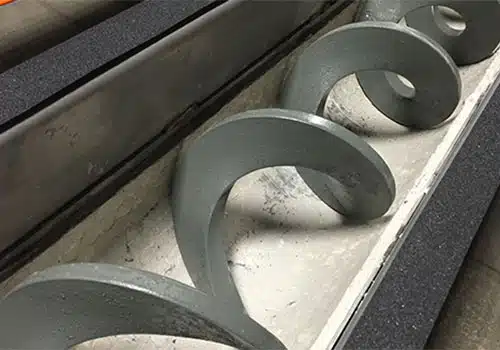
Shaftless Conveyor With Trough Liner
Figure 2. The ceramic lining enables smooth conveyance of wet or sticky materials. Source: KWS Manufacturing.
The screw conveyor’s full length must be aligned both horizontally and vertically. You should check for both horizontal and vertical misalignment every five feet with a measuring tape. Measuring the distance from the string line to the edge of the trough horizontally shows the screw conveyor misalignment in the horizontal direction. Similarly, measuring the distance from the string line to the trough flange’s bottom gives the vertical misalignment. Document each horizontal and vertical measurement. The relative differences in the measurements indicate how much you must move each trough section to achieve proper alignment.(For more information, see: “Screw Failures”)
Screw conveyors that are longer than, say, 25 ft, can create a common misalignment problem with multiple hanger bearing locations. Because the screw is fixed at the bearing locations, misalignment causes application of bending loads at the hanger locations that are immediately reversed during every revolution. The effect of these cyclical forces is similar to that of bending a paperclip back and forth until it breaks. Cyclical loading finds the weakest zone of the screw, which normally is close to the hanger bearings, in the screw bushing area. So, fatigue due to misalignment is the culprit for failures at or near the hanger bearings. This fatigue failure is the reason for a clean break in the affected area.
An alternative to multiple screw sections and hanger fatigue problems is to mount the screw on larger-diameter pipe with a heavier wall thickness to span longer distances, while decreasing deflection and eliminating the need for hanger bearings.
Products, Problems And Solutions
Some services call for use of stainless steel for all product-contact surfaces in the screw conveyor to prevent contamination or corrosion. Using a carbon steel screw in these applications isn’t appropriate; instead, a stainless steel ribbon screw (with a shaft) is the best option. To provide successful release of sticky material and avoid buildup, specify polishing of the ribbon screw flight surfaces or the entire screw to a fine finish or electropolishing to a mirror finish. Another option is coating the screw and conveyor surfaces with a nonstick material, such as polytetrafluoroethylene (PTFE), suitable for your application.
When conveying wet or sticky material, sticking product can lead to clogging and reduced capacity. In such services, an appropriate choice is a conveyor with shaftless screws without a center pipe to eliminate areas for the product to stick. Such a conveyor normally has a high-strength carbon steel spiral and a stainless steel trough with a reduced-friction liner and high-torque drive unit.
Conveying abrasive materials like titanium dioxide calls for screw conveyors manufactured from specific abrasion-resistant materials. Standard carbon steel and stainless steel components will wear rapidly in these applications, causing frequent conveyor maintenance and downtime. To avoid higher operating costs and premature equipment failure, opt for screw flights made from abrasion-resistant plates or have hard surfacing applied to the flights, pipe or troughs. The hard surfacing itself can comprise various blends of carbon, chromium, tungsten, cobalt, molybdenum and other exotic materials applied over softer standard construction materials to extend component life and decrease unnecessary downtime. The best combination for your application depends on the conveyor component’s base material, as well as your conveyed material, application requirements and operating environment. (See: “Screw Conveyor Solutions for Four Problem Applications”).
In a heat-transfer screw processor (also called a heating or cooling screw conveyor), a heating or cooling medium continuously circulates through a hollow trough jacket or the screw (or both) to move heat to or from the material. In the screw, the medium flows through the pipe or hollow flights.
Some bulk materials will tend to pack under pressure during conveying; this packing will form a hard layer in the bottom of the housing. Often, the layer will break loose in pieces and be conveyed downstream. Then, a new layer will form and again break loose. In rare applications, a bulk material will create a permanent layer in the housing’s bottom. This layer will build up over time and result in screw deflection in the center. Because each screw end is held fixed by the bearings, the pushing up of the screw in the center causes enormous cyclical forces on the center pipe of the screw as it rotates. Every revolution of the screw results in a complete reversal of the center pipe’s forces. Fatigue failures often are simple to identify because the break is virtually perpendicular to the center line of the screw conveyor and typically occurs in the screw sections’ center. A solution is to add trough liners to decrease the gap between the outer diameter of the screw and the housing (Figure 2). If the material layer is very thin, then it will break loose and be transferred downstream. Using a ¼-in.-thick abrasion-resistant plate for the liner material will provide longer life than mild steel.
Adding cutter teeth or weld-on hard surfacing to the outer diameter of the screw flights is another option. This decreases the gap between the screw and housing as well as affords a surface to cut through the hardened layer. Carbide teeth on the outer diameter of the screw will cut through almost any hardened material in the housing.
As stated previously, the key to solving the problem is removing the hardened material in the bottom of the housing. Pairing use of liners with either mounting the screw on larger pipe or adding cutter teeth most certainly will solve just about any issue of this kind.
Solving A Specific Problem
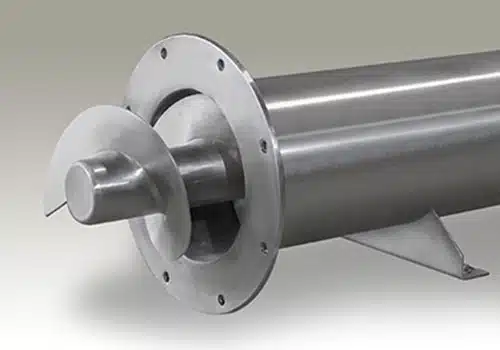
Cantilever Design
Figure 3. This effectively handles applications such as hydrofluoric residue conveying/bulk handling.
A processor used residue screws of a cantilever design (Figure 3) — in this case, a custom version, 17½-ft long and 11½-in. in diameter — for an application involving extreme temperatures, hazardous gases and abrasive product. To meet the plant’s preventative maintenance program for its equipment, the screws must last at least 9 months. Another supplier had attempted to reduce the cost of the screws with a solid shaft inserted the length of the pipe, but those screws only lasted 3–4 months before failure.
After a few meetings and site visits with a third-party specialist to see the equipment in operation, a new design was engineered. It features Hastelloy for better sealing, a custom drive shaft heat-shrunk deep into the pipe, sectional flighting with specific hard facing for the application and particular tolerances. The new design not only met the operating company’s price point target but also, more importantly, provided the design life needed. This has resulted in a large cost saving by avoiding unnecessary teardown of the equipment due to a failed screw.
Solid Advice
The centuries-old, simple and reliable screw conveyor remains the best option for many applications. Optimizing a device for a particular service requires an understanding of the factors that contribute to a screw conveyor’s performance and life. Making the right choices is the key to increased production and elimination of unnecessary downtime and maintenance costs.
Jim Collins is executive vice president of KWS Manufacturing, Burleson, Texas. Aaron Mire is a sales manager, based in Gonzales, La., for Motion Industries. Email them at [email protected] and [email protected].