Screw Conveyor Capacity
Calculation Of Conveyor Speed Capacity Factors for Special Pitches Capacity Factors for Modified Flight Capacity TableCapacity is defined as the weight or volume per hour of a bulk material that can be safely and feasibly conveyed using a screw conveyor. Screw conveyor diameter is determined by multiple factors including capacity.
The following steps are required for proper screw conveyor selection:
- Calculate required capacity in cubic feet per hour (ft3/hr).
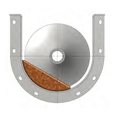
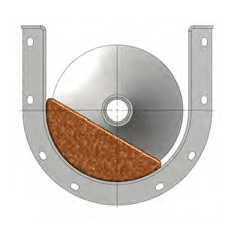
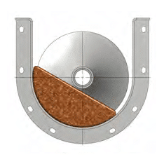
- Select the recommended trough loading percentage from the Bulk Material Table for the specific bulk material to be conveyed.
- Select the screw conveyor diameter that corresponds with the recommended trough loading and is less than the capacity at maximum RPM from the Capacity Table.
- Calculate actual conveyor speed by dividing the required capacity by the capacity at 1-RPM from the Capacity Table.
NOTE: Maximum speeds shown in the Capacity Table are not intended for every application and were developed for non-abrasive, free-flowing bulk materials. KWS recommends lower screw conveyor speeds for most industrial applications. A larger screw conveyor diameter will be required for lower screw conveyor speeds.
Maximum lump size must also be considered when designing a screw conveyor. Please refer to the Bulk Material Lump Size section for further information.
The Capacity Table is only intended for designing control fed screw conveyors. Conversely, screw feeders are flood loaded at the inlet and require special design considerations. Please refer to the Screw Feeder section for further information.
Calculation Of Conveyor Speed
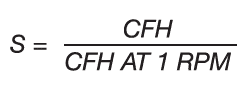
The maximum recommended capacity for each screw diameter is listed in the Capacity Table for reference and should not be exceeded. Using the formula below, the exact conveyor speed (S) can be calculated:
Nomenclature:
S = Conveyor Speed
CFH = Capacity in Cubic Feet per Hour (ft3/hr)
Capacity Factors for Special Pitches
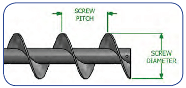
Screw conveyors transfer bulk materials volumetrically and capacity is calculated in cubic feet per hour. Screw conveyor capacity is affected when the flight pitch is reduced from standard full pitch. Reducing the flight pitch reduces the capacity. For example, a 1/2 pitch screw carries 1/2 the capacity of a full pitch screw at the same level of trough loading and speed. Capacity Factors for Special Pitches are shown below.
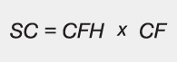
Selection Capacity (SC) is the capacity adjusted for special pitch or modified flights used in the process of selecting the screw conveyor diameter for the application.
Calculation of special screw conveyor capacities is as follows:
Nomenclature:
SC = Selection Capacity
CFH = Required Capacity in Cubic Feet per Hour (ft3/hr)
CF = Capacity Factor
| Capacity Factors for Special Pitches | ||
|---|---|---|
| Pitch | Description | Capacity Factor |
| Standard | Pitch = Diameter | 1.00 |
| Short | Pitch = 2/3 Diameter | 1.50 |
| Half | Pitch = 1/2 Diameter | 2.00 |
| Long | Pitch = 1-1/2 Diameters | 0.67 |
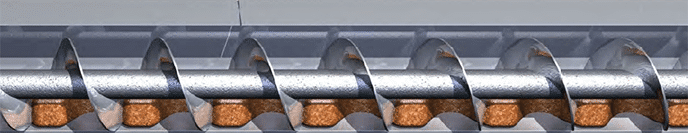
Capacity Factors for Modified Flight
Screw conveyor capacity is also affected by using modified flight types such as cut flight, cut-and-folded flight, ribbon and paddles. The use of modified flights reduces conveying capacity. Capacity Factors for Modified Flights are shown below for various flight types and trough loading.
| Capacity Factors for Cut or Cut and Fold Flights |
|||
|---|---|---|---|
| Flight Type | Conveyor Loading | ||
| 15% | 30% | 45% | |
| Cut flight | 1.92 | 1.57 | 1.43 |
| Cut & folded flight | X | 3.75 | 2.54 |
| Capacity Factors for Paddles | ||||
|---|---|---|---|---|
| Paddles Per Pitch | 1 | 2 | 3 | 4 |
| Factor | 1.08 | 1.16 | 1.24 | 1.32 |
| Capacity factors for ribbon flights | |||
|---|---|---|---|
| Ribbon Screw dia. | Conveyor Loading | ||
| 15% | 30% | 45% | |
| 4 | X | X | X |
| 6 | 1.32 | 1.52 | 1.79 |
| 9 | 1.34 | 1.54 | 1.81 |
| 12 | 1.11 | 1.27 | 1.50 |
| 14 | 1.27 | 1.45 | 1.71 |
| 16 | 1.55 | 1.69 | 1.90 |
| 18 | 1.33 | 1.53 | 1.80 |
| 20 | 1.60 | 1.75 | 1.96 |
| 24 | 2.02 | 2.14 | 2.28 |
| 30 | 2.16 | 2.29 | 2.44 |
| 36 | 3.27 | 3.37 | 3.70 |
Example
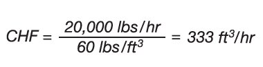
A screw conveyor is required to transport 10 tons per hour of unslaked lime with a bulk density of 60 lbs/ft3. The unslaked lime also needs to be mixed in transit using cut and folded flights. The conveying distance is 15-feet, so short (2/3) pitch screws will be used to ensure proper mixing. The recommended trough loading percentage from the Bulk Material Table is 30A.
Actual calculated capacity is:
For proper selection of screw conveyor diameter and speed, the actual capacity must be adjusted for the cut and folded flights and short pitch using the Capacity Factors for Special Pitches and Modified Flights. As stated above, the adjusted capacity is defined as Selection Capacity (SC).
The Capacity Factor for short (2/3) pitch is 1.50.
| Capacity Factors for Special Pitches | ||
|---|---|---|
| Pitch | Description | Capacity factor |
| Standard | Pitch = Diameter | 1.00 |
| Short | Pitch = 2/3 Diameter | 1.50 |
| Half | Pitch = 1/2 Diameter | 2.00 |
| Long | Pitch = 1-1/2 Diameters | 0.67 |
The Capacity Factor for cut and folded flights with 30-percent trough loading is 3.75.
| Capacity Factors for Cut or Cut and Fold Flights |
|||
|---|---|---|---|
| Flight Type | Conveyor Loading | ||
| 15% | 30% | 45% | |
| Cut flight | 1.92 | 1.57 | 1.43 |
| Cut & folded flight | X | 3.75 | 2.54 |
Therefore:
SC = 1.50 X 3.75 X 333 ft3/hr
SC = 1,873 ft3/hr
The Selection Capacity will be used to select the proper screw conveyor diameter and speed from the Capacity Table. With a recommended trough loading of 30A, the Selection Capacity must be less than the maximum capacity given in the Capacity Table. A 16-inch diameter screw conveyor will convey 2,496 cubic feet per hour at the maximum recommended speed of 80-rpm.
The actual screw conveyor speed is calculated by dividing the Selection Capacity by the capacity at 1-rpm.
1,873/31.2 = 60-rpm
60-rpm is the correct speed for a 16-inch diameter screw conveyor with cut and folded flights and short pitch for conveying and mixing 333 cubic feet per hour.
Capacity Table
| Trough Loading | Screw Dia. (in.) | Max. RPM * | Capacity in ft3/hr | |
|---|---|---|---|---|
| At Max. RPM | At 1 RPM | |||
 15% |
4 | 69 | 14.5 | 0.2 |
| 6 | 60 | 45 | 0.8 | |
| 9 | 55 | 150 | 2.7 | |
| 12 | 50 | 323 | 6.5 | |
| 14 | 50 | 520 | 10.4 | |
| 16 | 45 | 702 | 15.6 | |
| 18 | 45 | 1,012 | 22.5 | |
| 20 | 40 | 1,248 | 31.2 | |
| 24 | 40 | 2,184 | 54.6 | |
| 30 | 35 | 3,728 | 106.5 | |
| 36 | 30 | 5,532 | 184.4 | |
 30% A |
4 | 139 | 57 | 0.4 |
| 6 | 120 | 179 | 1.5 | |
| 9 | 100 | 545 | 5.5 | |
| 12 | 90 | 1,161 | 12.9 | |
| 14 | 85 | 1,768 | 20.8 | |
| 16 | 80 | 2,496 | 31.2 | |
| 18 | 75 | 3,375 | 45.0 | |
| 20 | 70 | 4,375 | 62.5 | |
| 24 | 65 | 7,085 | 109.0 | |
| 30 | 60 | 12,798 | 213.3 | |
| 36 | 50 | 18,440 | 368.8 | |
 30% B |
4 | 69 | 28 | 0.4 |
| 6 | 60 | 90 | 1.5 | |
| 9 | 55 | 305 | 5.5 | |
| 12 | 50 | 645 | 12.9 | |
| 14 | 50 | 1,040 | 20.8 | |
| 16 | 45 | 1,404 | 31.2 | |
| 18 | 45 | 2,025 | 45.0 | |
| 20 | 40 | 2,500 | 62.5 | |
| 24 | 40 | 4,360 | 109.0 | |
| 30 | 35 | 7,465 | 213.3 | |
| 36 | 30 | 11,064 | 368.8 | |
 45% |
4 | 190 | 116 | 0.61 |
| 6 | 165 | 368 | 2.2 | |
| 9 | 155 | 1,271 | 8.2 | |
| 12 | 145 | 2,813 | 19.4 | |
| 14 | 140 | 4,368 | 31.2 | |
| 16 | 130 | 6,071 | 46.7 | |
| 18 | 120 | 8,112 | 67.6 | |
| 20 | 110 | 10,307 | 93.7 | |
| 24 | 100 | 16,400 | 164.0 | |
| 30 | 90 | 28,800 | 320.0 | |
| 36 | 75 | 41,490 | 553.2 | |
NOTE: Maximum speeds shown in the Capacity Table are not intended for every application and were developed for non-abrasive, free-flowing bulk materials. KWS recommends lower screw conveyor speeds for most industrial applications. A larger screw conveyor diameter will be required for lower screw conveyor speeds.